

1. Overview
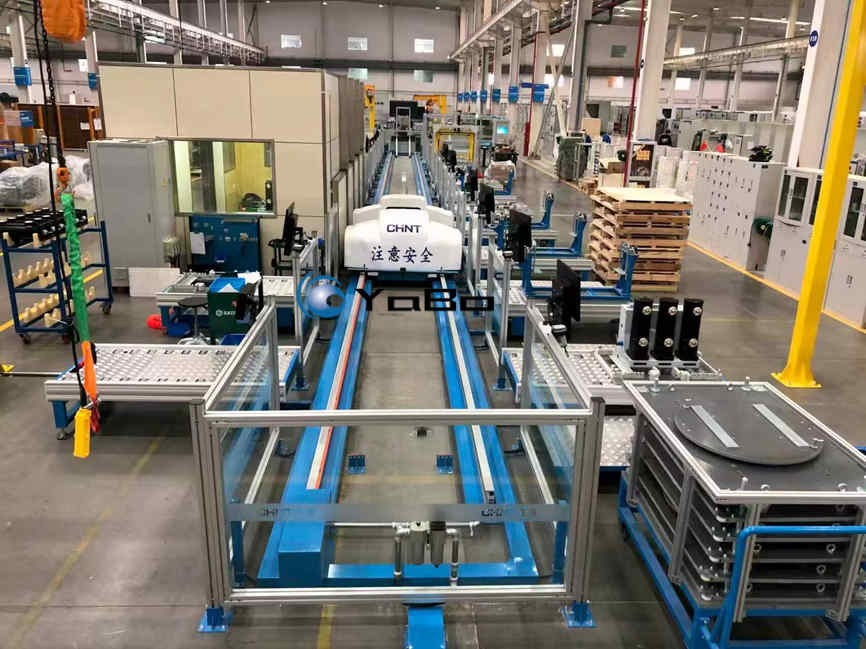
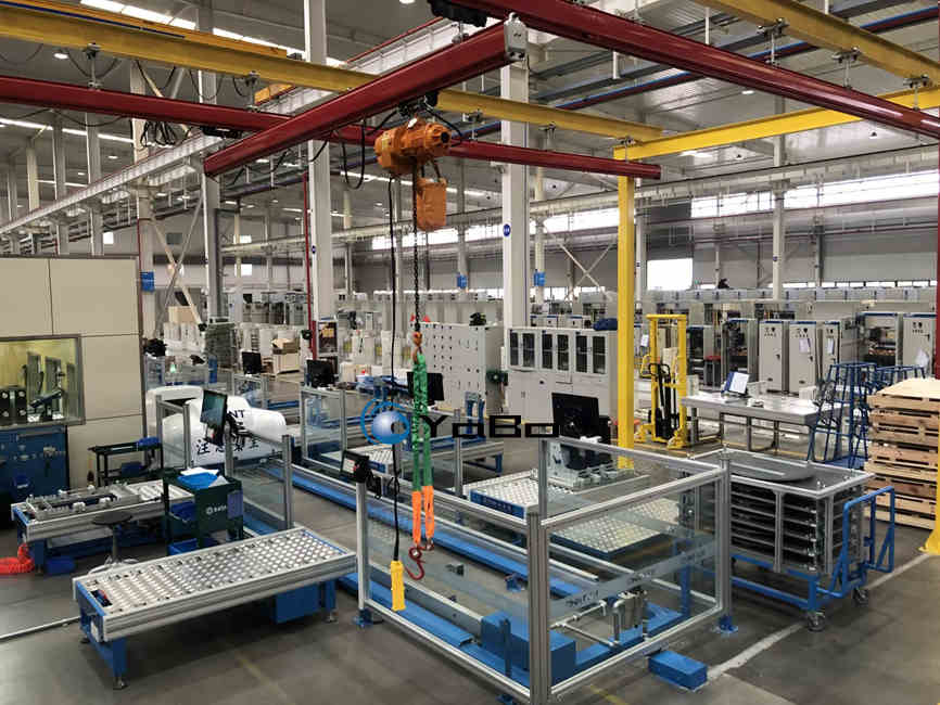
The VCB assembly line is a modular final-assembly system for vacuum circuit breakers rated 12, 24, 36 and 40.5 kV, built around one or more rail-guided vehicles (RGVs). A floor-mounted rail runs the length of the line; the RGV carriage carries the breaker from station to station and locks into position at each stop. Stations stand on both sides of the track, each with its own fixture, tooling, part racks and MES terminal. Torque-controlled fastening, mechanical-characteristic adjustment, routine testing and MES traceability are integrated in one flow, configured around the breaker family, annual volume and takt time of the plant.
The line is used by breaker manufacturers and switchgear plants producing indoor VCBs (VS1, VD4, ZN28 class), outdoor VCBs, smart breakers and RMU modules for KYN28, KYN61 and XGN switchgear. It can be installed as a new line, as a capacity expansion, or as a replacement for an existing circuit breaker assembly line.
The RGV replaces the fixed conveyor with a vehicle that can be routed. A station can be added, reordered or bypassed for repair and rework without rebuilding the track; a second vehicle can be added when volume grows; and one track can carry different model variants. At the end of the line the breaker is tested, data-uploaded and released to packaging. Depending on configuration, a VCB assembly line covers 10,000–50,000 units a year on two shifts.
None of the RGV parameters is a catalogue number. Vehicle count, rail gauge and length, payload, positioning accuracy, speed and power supply — and whether one vehicle serves one line, several lines or different products — are project variables, set by the breaker family, the takt and the building rather than by a standard model list.
Line composition
- RGV transport: floor-mounted rail, servo-driven carriage, custom load (typically 50–500 kg), positioning accuracy ±0.5–1 mm, bidirectional travel, anti-collision sensors; power by conductor rail, cable chain or battery.
- Stations: aluminium-extrusion workstations on both sides of the track, with clear polycarbonate guards, dedicated fixture, calibrated torque tools, part racks and HMI/MES terminal.
- Fixtures: machined aluminium fixture plates and quick-change nests; heavy poles and mechanisms are loaded with the crane.
- Handling: KBK light crane with electric hoist, 0.5–5 t, over the track.
- Test bay: mechanical-characteristic tester, contact-resistance meter, AC withstand set, insulation tester, optional partial-discharge set.
- MES: electronic BOM and work instructions, torque and test data capture, serial-number traceability, OPC UA interface.
- Safety: polycarbonate guards, light curtains, safety doors, LOTO points; RGV bumpers and a safety laser scanner.
Key features
- RGV flexibility. Stations can be added, reordered or bypassed; the layout can be straight, U-shaped, looped or branched; mixed 12/24 kV models share the track.
- Capacity by vehicle count. Throughput is tuned by RGV speed and the number of vehicles, not by rebuilding the conveyor; a second RGV covers volume growth or vehicle downtime.
- Precise docking. Servo drive and a secondary locator give repeatable stops for torque and test; the unit is clamped and referenced before work starts.
- Fast changeover. Quick-change fixture plates and model nests keep model switching in minutes.
- Controlled fastening. Electric or servo torque tools with ±3–5% control; every safety-critical joint is recorded.
- Traceable quality. Each breaker’s serial number is bound to station, operator, torque values and test results.
- Test capacity matched to takt. The test bay is sized by test time, not assembly time.
- Targeted automation. Heavy handling, torque and test data are automated; fine assembly and wiring stay manual.
2. VCB Assembly Process
The process below is the standard configuration of our circuit breaker assembly line. The RGV delivers the unit to each station, and the unit is clamped and referenced before any force or torque is applied.
- Incoming inspection. Each vacuum interrupter is checked for vacuum integrity by power-frequency withstand (42 kV, 1 min for the 12 kV class), contact resistance and mounting dimensions; epoxy poles for cracks and inserts; mechanisms, CTs and auxiliary switches against the drawing.
- Mechanism pre-assembly. Spring mechanism, main shaft and linkage are assembled on a fixture and exercised by hand: energy storage, closing, opening, no binding. Fasteners are tightened to the specified torque with calibrated tools.
- Pole assembly. The interrupter is mounted into its pole, fixed and moving contacts are fitted and the linkage connected. Pressing and alignment are done in a guided fixture so the interrupter sees axial force only.
- Three-pole assembly. Poles are mounted on the frame, phase spacing and verticality are set, and the main circuit is connected. Busbar joints and contact arms carry the highest torque values on the product.
- Secondary wiring. Auxiliary switches, opening and closing coils, anti-pumping relays, CT/PT wiring and, on smart breakers, the sensor and communication module. Wires are routed, labelled and continuity-tested; smart secondary assemblies are aged before final build.
- Mechanical adjustment. Contact gap (typically 8–12 mm at 12 kV), overtravel, contact pressure, opening and closing speeds, contact bounce and three-phase synchronism (about 2 ms) are measured and adjusted. A mechanical-characteristics tester records the curves, which are compared with the type-test window.
- Routine tests. Per IEC 62271-100 and GB/T 1984: power-frequency withstand (42, 65 or 95 kV for 12, 24 and 40.5 kV, 1 min), main-circuit resistance (typically ≤50 μΩ and never above 1.2 times the type-test value), insulation resistance, mechanical operation sequences and secondary functional checks; partial-discharge testing for 24 kV and 40.5 kV where specified.
- Final inspection and release. Nameplate, accessories, appearance and packaging are checked, and the unit data is uploaded. Every breaker leaves with a record binding its serial number to station, operator, torque values and test results.
Takt balance is set at the layout stage: vehicle count, RGV speed and station split are chosen so that no station exceeds the takt time; buffers and parallel test positions absorb the difference between assembly and test duration.
3. Customizable Parameters of the VCB Assembly Line
The table lists the variables we configure. There is no fixed model number for an RGV assembly line: vehicle count, rail gauge and length, payload, accuracy, speed and power supply follow from the product, the takt and the building. Items marked custom are engineered per project.
| Category | Parameter | Options / range | Design note |
|---|---|---|---|
| Product | Breaker type | Indoor VCB (VS1/VD4/ZN28 class), outdoor VCB, smart VCB, RMU module | Fixtures and test plan follow the family |
| Product | Voltage class | 12 / 24 / 36 / 40.5 kV | Test equipment scales with kV |
| Product | Rated current | 630–4,000 A | Busbar torque and heat-run criteria |
| Product | Breaking capacity | 20–50 kA | Test bay and interlocks |
| Product | Mounting | Fixed / withdrawable / truck-mounted | Fixture locates the truck or frame |
| Line | Transport | RGV rail-guided vehicle (standard); AGV or pallet conveyor optional | Routing flexibility vs volume |
| Line | RGV count | 1–4 vehicles, project-set; single or multiple | Takt, redundancy and growth |
| Line | Vehicle service | Dedicated to one line / shared by several lines / multi-product | Layout and utilisation |
| Line | Rail layout | Straight / U-shape / loop / branched | Building shape and process route |
| Line | Rail gauge | Custom, typically 600–3,000 mm | Product size and building |
| Line | Positioning accuracy | ±0.5–1 mm (custom; ±0.1 mm with secondary locator) | Torque and test repeatability |
| Line | RGV load | 50–500 kg (custom) | Breaker plus fixture weight |
| Line | RGV speed | 0.2–1.0 m/s (custom) | Travel time vs takt |
| Line | Power supply | Conductor rail / cable chain / battery | Layout and maintenance |
| Line | Control and communication | PLC + HMI; wireless / optical / inductive link; MES via OPC UA | Integration with plant systems |
| Line | Stations | 12–60, two-sided | Process split and takt balance |
| Line | Station fixtures | Aluminium fixture plate, quick-change nests | Changeover target (SMED) |
| Line | Takt time | 3–15 min per unit | Set with vehicle count and speed |
| Line | Track length | 30–150 m (custom) | 1.2–2.5 m per station per side |
| Line | Expandability | Pre-wired for added stations and vehicles | Phased investment |
| Automation | Automation level | Manual / semi-automatic / robotic cell | Justify by volume and labour cost |
| Automation | Heavy handling | KBK crane 0.5–5 t / gantry servo press / robot | Pole and mechanism weight |
| Automation | Fastening | Pneumatic / electric / servo torque (±3–5%) | Safety-critical joints |
| Automation | Vision | Barcode/2D code reading, presence checks, OCR | Poka-yoke and traceability |
| Automation | Logistics | Manual carts / AGV-AMR | Layout and WIP policy |
| Test | Test scope | Mechanical characteristics, contact resistance, AC withstand, insulation resistance, PD (24/40.5 kV), functional | Per IEC 62271-100 / GB/T 1984 |
| Test | Test bay | In-house or third-party equipment, capacity matched to takt | Test time often equals assembly time |
| Data | MES / SCADA | Barcode/RFID, OPC UA, torque and test data, dashboards | Unit-level traceability |
| Environment | Cleanliness | Standard shop / clean-room option | VGC and pole assembly |
| Environment | Temperature / humidity | 23±5 °C, ≤60% RH | Epoxy and insulation handling |
| Utilities | Power / air | 380 V 50 Hz or 400/480 V 60 Hz; 0.6–0.8 MPa | Local plant standard |
| Safety | Guarding | PC panels, light curtains, safety doors, LOTO; RGV bumper and laser scanner | CE / ISO 12100 / IEC 60204-1 |
| Project | Delivery | 12–24 weeks typical | After design freeze |
| Project | Services | FAT/SAT, installation, training, spares, warranty | Remote diagnostics option |
Request a Configuration
To specify a VCB assembly line — a new build or a replacement of an existing circuit breaker production line — send the breaker family, annual volume, takt target and floor plan. We will return a station list, RGV layout, fixture concept and test-bay sizing, with the assumptions stated.