

1. Overview
The Pole-Mounted Switch Assembly Line is a flexible manufacturing and assembly system developed specifically for high-voltage distribution switchgear in the 10kV power distribution sector, including primary-secondary integrated pole-mounted circuit breakers, demarcation switches, and pole-mounted load switches. It integrates mechanical conveying, specialized process equipment, electrical control, and industrial informatization into a single production line. Covering the three key stages of assembly, commissioning, and testing, the system is designed to enable switches to complete a continuous process chain from shell loading to finished product discharge.
Historically, such products were largely manufactured using dispersed workstations and manual assembly. Shells, operating mechanisms, poles, and secondary circuits were handled separately and transported via overhead cranes and transfer carts. Assembly sequence, torque application, and wiring points relied heavily on worker experience, making it difficult to ensure consistency even between two units of the same batch. Furthermore, factory acceptance testing was often separated from the assembly site, complicating root cause analysis when issues arose due to incomplete records. This pole-mounted switch assembly line addresses these challenges by standardizing processes, ensuring every unit follows an identical production path, and capturing comprehensive process data throughout.
1.1 Operating Principle
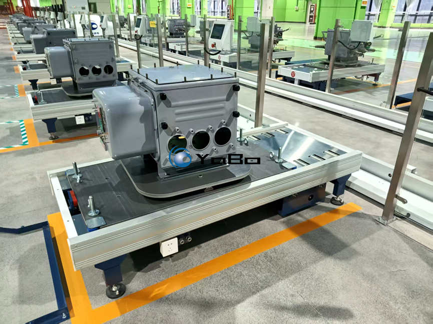
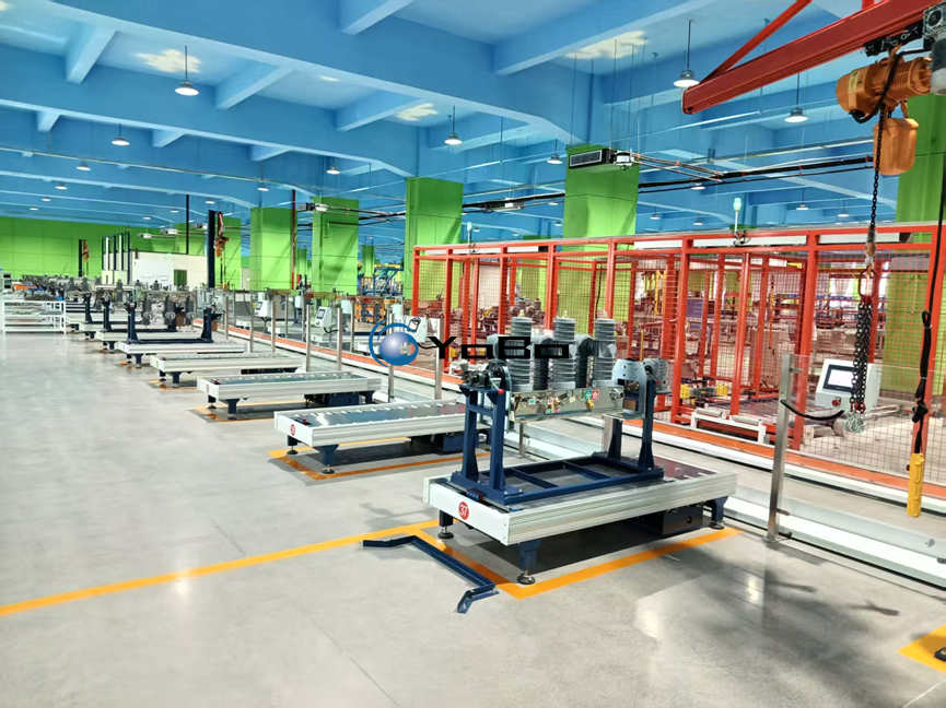
The entire line utilizes customized tooling pallets as the baseline for product carrying and positioning. At the first station, the switch shell is hoisted onto the pallet, which then travels along the conveyor track through each sequential workstation. The pallet features built-in positioning and locking mechanisms and offers rotation and tilting capabilities at multiple stations to facilitate ergonomic assembly angles. After the finished product is unloaded at the final station, empty pallets automatically return to the starting point via a return track, forming a closed-loop cycle.
This production model clearly defines station responsibilities: downstream stations do not need to rework processes completed upstream. If an anomaly occurs at a specific station, the unit can be isolated at a dedicated repair station without disrupting the flow of other pallets. Production is organized based on pallet position rather than team shifts, making the takt time calculable and adjustable.
1.2 Flexible Adaptability
Manufacturing facilities typically handle multiple product series simultaneously. Significant structural differences exist between circuit breakers and load switches, while demarcation types and sectionalizing/tie-switch types vary in their configuration of instrument transformers, potential transformers (PTs), and connecting cables, resulting in substantial variations in dimensions and weight. Rather than being a dedicated line for a single product, this assembly line accommodates model changeovers by replacing tooling locating elements and loading corresponding operational programs, leaving the main conveyor structure unchanged. A typical changeover involves only tooling adjustment and program loading, with no need to reconfigure the track layout.
In terms of compatibility, the primary side covers pole-mounted vacuum circuit breakers, demarcation circuit breakers, sectionalizing/tie circuit breakers, pole-mounted load switches, and demarcation load switches. The secondary side encompasses Feeder Terminal Units (FTUs), instrument transformers, PTs, aviation connectors, and outdoor connecting cables. When new models are introduced, corresponding tooling and programs can be added provided that product drawings, assembly processes, and test items are clearly defined. The line itself imposes no upper limit on product variety; constraints are limited only by tooling load capacity and workstation operating space.
1.3 Customization Dimensions
As a non-standard integrated equipment system, this pole-mounted switch assembly line is not available as an off-the-shelf standard model. The solution design phase must simultaneously address three factors: the customer’s facility layout, column grid, and door dimensions determine the line configuration and overall length; annual capacity targets and shift patterns determine the number of workstations and takt time; and the product portfolio and assembly drawings determine tooling structures and test requirements.
Regarding layout, a linear configuration is adopted when floor space permits, offering clear visibility of upstream and downstream processes. Where length is constrained, U-shaped or back-and-forth layouts are employed, utilizing return sections to convey empty pallets back to the start; this requires allocating additional space at corners for transfer and maintenance access. The number of workstations is also adjustable: a base configuration of eight stations is common, with additional stations inserted as needed for tightening, leak testing, marking, etc., along with reserved repair and buffer stations.
1.4 Informatization and Traceability
Product serial numbers are entered at the first station. Thereafter, process confirmations, critical parameters, and anomaly records at every subsequent station are linked to that serial number, creating a complete digital record for each unit. For batch traceability, users can retrieve assembly timestamps, operator IDs, tightening data, burn-in curves, and test results by serial number, eliminating reliance on paper travelers.
MES integration is optional. When connected, the assembly line receives work orders and feeds back four status categories—started, completed, WIP (work-in-progress), and exception—along with order-level output and yield rates. For customers without MES, the line’s built-in local data storage is sufficient to support unit-level traceability. Interfaces utilize standard industrial protocols, with specific data fields confirmed against the customer’s information systems during the solution design phase to avoid post-installation rework.
1.5 Safety Design
The production area is enclosed by safety guarding fences. Personnel access points are equipped with safety interlocks and emergency stop circuits; opening a gate triggers an immediate line stop. Lifting assist devices are sized according to shell weight to reduce manual handling burdens. Audible and visual alarms provide distinct signals for three states: pallet arrival, fault stop, and reset permission. Tooling tilt and rotation movements incorporate travel limits and position confirmation sensors; failure to lock prevents advancement to the next station. These measures are implemented in tiers according to the customer’s workshop safety management policies, with specific configurations detailed in the proposal.
2. Core Process Flow
The pole-mounted switch assembly line employs a pallet-return production model: pallets carrying workpieces pass sequentially through each station according to the process flow to complete all assembly and commissioning tasks. After finished products are discharged, empty pallets return to the starting station via the return track for reuse. The following section describes, in station order, what each station does, the required completion criteria, and the records generated. Station sequence and quantity may be adjusted according to customer-specific processes and are not required to match the table below exactly.
Table 2-1: Base Station Operations Overview
| Station | Operation Content & Control Points |
|---|---|
| Shell Loading | Overhead crane lifts the switch shell onto the tooling pallet; tooling completes positioning and locking. Built-in tilt/rotation mechanism adjusts the shell to the optimal angle for subsequent assembly. Product serial number is entered at the station terminal, binding the production record and establishing the starting point for unit traceability. |
| Internal Mechanism Assembly | Installation of core mechanical components including operating mechanism, transmission linkages, and spring assemblies; alignment and pre-tightening are completed. Pallet rotation/tilting eliminates blind spots and reduces repeated lifting/repositioning. Station records completion status; release is blocked until confirmation is received. |
| HV Pole Assembly | Assembly of high-voltage components including vacuum interrupter poles, insulating bushings, and inlet/outlet insulators; positioning and bolt tightening are completed. Installation accuracy directly impacts insulation performance; this station includes explicit checks for positioning datums and tightening torque. |
| Mechanical Assembly | Installation of external transmission parts, sealing components, enclosure doors, and accessories; enclosure sealing is completed. Mechanical transmission clearances are inspected point-by-point to confirm smooth operation without binding or abnormal friction. |
| Secondary Wiring | Completion of secondary control circuit, instrument transformer, and controller wiring; signal and power cables are routed and terminated. Station may include wiring guidance prompts with point-by-point verification against drawing numbers to prevent miswiring, missed connections, or reversed wire sequences. |
| Open/Close Burn-in & Commissioning | Multiple open/close cycles are performed for mechanical burn-in. Parameters including operating speed, travel distance, and three-phase synchronization are recorded. Mechanism action is commissioned to identify binding, incomplete travel, or abnormal bouncing. Curve data is archived under the product serial number. |
| Electrical Performance Testing | Execution of factory acceptance tests: main circuit resistance measurement, insulation testing, secondary circuit continuity check, etc. Circuit resistance is measured using the DC voltage drop method with test current ≥100A; before measurement, confirm the switch is closed and reliably grounded; after measurement, wait for instrument discharge before disconnecting. Non-conforming units are flagged online and routed to the exception handling station. |
| Finished Product Discharge | Qualified products are lifted off the tooling pallet by crane and transferred to finished goods storage. Unloaded empty pallets enter the return track and are automatically conveyed back to the starting station for reuse. |
2.1 Optional Extended Stations
Beyond the base stations, the following may be inserted as required by process needs: servo-driven automatic tightening stations (for high-volume bolt operations requiring consistent torque); robot-assisted assembly/loading-unloading stations (for highly repetitive tasks or confined spaces); leak testing stations (for SF6-filled or moisture-sealed products); and identification/marking stations (linking nameplates, QR codes, and serial numbers). Extended stations share the same control and data architecture as base stations, requiring no separate system.
2.2 Data Acquisition & Station Terminals
Each station is equipped with an independent HMI touchscreen serving three functions: process confirmation (completion status and release authorization), data acquisition (manual entry or automatic capture of key parameters), and anomaly alerting (missing process steps, out-of-tolerance values, equipment faults). All process data is centrally stored and searchable by product serial number, shift, station, and time period. Alarm records and resolution outcomes are retained together to facilitate analysis of recurring issues.
3. Key Technical Specifications
The following table provides reference indicators for preliminary evaluation during the solution selection phase. All hardware specifications, process stations, and control functions must be custom-designed based on customer product drawings, capacity targets, and facility conditions. Items marked “Optional” are not included in standard delivery scope.
Table 3-1: Key Technical Specifications (All Support Non-Standard Customization)
| Item | Specification Description |
|---|---|
| Compatible Products | Various 10kV pole-mounted vacuum circuit breakers, demarcation switches, primary-secondary integrated pole-mounted switches, and pole-mounted load switches. Supports mixed-model production across various dimensions and weights; product range expandable as needed. |
| Conveyor System | Recirculating pallet/skid conveyor; pallets feature positioning/locking mechanisms and support workpiece rotation and multi-angle tilting. Load capacity and dimensions customized to actual customer products. |
| Station Configuration | Base stations configurable up/down; expansion stations reserved. Additional exception repair and buffer stations available. Station count determined by capacity requirements. |
| Production Takt Time | Custom-designed per customer capacity targets; takt time adjustable; compatible with multi-variant changeover production. |
| Power & Air Supply | Compatible with 380V industrial power supply and 0.4–0.7 MPa compressed air; adaptable to site-specific utility conditions. |
| Control System | Centralized PLC control with independent HMI at each station; fault alarm and station status monitoring included. Supports MES integration for work order dispatch, production data collection, and full lifecycle traceability (MES integration is optional). |
| Layout Configuration | Standard linear type; U-type or back-and-forth layouts available for space-constrained facilities. Length, width, and height designed per facility dimensions. |
| Ancillary Hardware | Station-assist lifting fixtures, safety guarding fences, E-stop safety interlocks, audible/visual alarms, pallet return conveyor system. All ancillary components selectable as needed. |
| Optional Expansion Modules | Servo auto-tightening unit, leak test module, robot-assisted loading/unloading & assembly, auto-marking/identification, inline electrical test module. Integrated on demand. |
| Operating Environment | Suitable for standard indoor HV switchgear assembly workshops. Protective customization available based on workshop temperature/humidity and dust conditions. |
3.1 Test Item Notes
Acceptance criteria for factory tests conducted at the Electrical Performance Testing station are derived from product technical specifications and applicable test standards; uniform numerical values are not provided herein. Main circuit resistance limits, insulation levels, and mechanical characteristic thresholds vary significantly across models and must be set according to specific product datasheets. The role of the assembly line is to parameterize these criteria within the test program, ensuring consistent limits and wiring configurations for every test, with automatic pass/fail determination.
Taking open/close burn-in as an example, parameters to be recorded include opening time, closing time, three-phase non-simultaneity, operating speed, and contact travel (gap). For 10kV-class equipment, typical limits for three-phase closing and opening non-simultaneity are ≤2 ms, subject to specific product technical conditions. When synchronization exceeds tolerance, adjustment typically begins with verifying the effective length of each phase’s transmission linkage; however, travel and over-travel must first be confirmed within specification, otherwise synchronization adjustments lack a valid reference baseline.
3.2 Items Requiring Confirmation for Non-Standard Solutions
Table 3-2: Solution Design Input Checklist
| No. | Input Item | Scope of Impact |
|---|---|---|
| 1 | Product portfolio, dimension & weight range | Tooling structure, load-bearing design, tilt mechanism selection |
| 2 | Assembly drawings & process documentation | Station task allocation, tooling datum definition, test items |
| 3 | Annual capacity, shift pattern, takt time requirements | Number of stations, buffer capacity, total line length |
| 4 | Facility floor plan (incl. column grid, doors, flooring) | Layout configuration, equipment foundation, logistics aisles |
| 5 | Power capacity & air supply conditions | Electrical distribution scheme, pneumatic circuit design |
| 6 | MES / IT interface requirements | Data fields, communication protocol, go-live scope |
| 7 | Safety & environmental management policies | Protection rating, interlock classification, dust/exhaust treatment |
3.3 Remarks
This pole-mounted switch assembly line is a non-standard integrated equipment system. The indicators in Table 3-1 serve as baseline references only and do not constitute performance commitments for any specific project. All hardware specifications, process stations, and control functions shall be developed into a dedicated solution based on customer product drawings, capacity targets, and on-site facility conditions, subject to mutual technical confirmation. Upon solution sign-off, the delivery scope, acceptance methodology, and acceptance criteria shall be finalized accordingly.